DMVPN Phase1 with RIA and failover to DIA
Introduction
DMVPN with Remote Internet Access (RIA) centralizes internet breakout through the Hub, keeping all Spoke traffic under consistent policy control. However, when the Hub becomes unreachable, Spokes need a fallback—that is where Direct Internet Access (DIA) failover comes in.
This lab demonstrates a DMVPN Phase 1 deployment utilizing RIA, supplemented by dynamic routing and policy-based DIA failover. This design ensures that connectivity remains intact when it matters most, automatically keeping branch offices online during a Hub outage.
Lab Topology
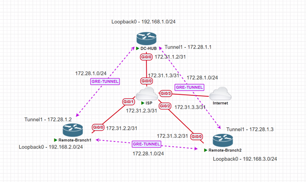
| Device | Role | Interfaces | IP Addresses |
| ISP | ISP | Gi0/0, Gi0/1, Gi0/2 | 172.31.1.3, 172.31.2.3, 172.31.3.3 |
| DC-HUB | DMVPN HUB | Gi0/0, Tunnel1, Loopback0 | 172.31.1.2, 172.28.1.1, 192.168.1.1 |
| Remote-Branch1 | DMVPN Spoke1 | Gi0/0, Tunnel1, Loopback0 | 172.31.2.2, 172.28.1.2, 192.168.2.1 |
| Remote-Branch2 | DMVPN Spoke2 | Gi0/0, Tunnel1, Loopback0 | 172.31.3.2, 172.28.1.3, 192.168.3.1 |
Theory & Background
DMVPN is Cisco's scalable VPN architecture utilizing mGRE tunnels, NHRP for dynamic Spoke address resolution, and IPsec for encryption. In an RIA design, all Spoke internet traffic routes through the Hub for centralized policy enforcement.
The drawback is Hub dependency. DIA failover solves this by keeping a local internet link on standby at each Spoke. This is activated automatically via floating static routes and EIGRP the moment the Hub becomes unreachable.
Step-by-Step Configuration
Step 1: Base Interface Configuration
First, we configure the basic IP addressing and NAT boundaries for the WAN and LAN interfaces on the Hub and both Spokes.
Hub Interface Configuration
interface GigabitEthernet0/0 // This is our WAN interface.
description Towards ISP
ip address 172.31.1.2 255.255.255.254
ip nat outside
ip virtual-reassembly in
duplex auto
speed auto
media-type rj45
end
interface Loopback0 // T
description HUB-LAN
ip address 192.168.1.1 255.255.255.0
ip nat inside
ip virtual-reassembly in
end
Spoke 1 Interface Configuration
interface GigabitEthernet0/0
description towards ISP
ip address 172.31.2.2 255.255.255.254
ip nat outside
ip virtual-reassembly in
duplex auto
speed auto
media-type rj45
end
interface Loopback0
description Remote-Branch1 LAN
ip address 192.168.2.1 255.255.255.0
ip nat inside
ip virtual-reassembly in
end
Spoke 2 Interface Configuration
interface GigabitEthernet0/0
description towards ISP
ip address 172.31.3.2 255.255.255.254
ip nat outside
ip virtual-reassembly in
duplex auto
speed auto
media-type rj45
end
interface Loopback0
description Remote-Branch2
ip address 192.168.3.1 255.255.255.0
ip nat inside
ip virtual-reassembly in
end
Step 2: DMVPN Tunnel Configuration
Next, we build the mGRE tunnels and configure NHRP. Notice that the Hub injects a default route down the tunnel for RIA using ip summary-address eigrp.
Hub Tunnel Configuration
interface Tunnel1
ip address 172.28.1.1 255.255.255.0
no ip redirects
ip hold-time eigrp 10 10
ip nat inside
ip nhrp authentication cisco123
ip nhrp network-id 10
ip virtual-reassembly in
ip summary-address eigrp 10 0.0.0.0 0.0.0.0
tunnel source GigabitEthernet0/0
tunnel mode gre multipoint
tunnel key 10
end
Spoke1 Tunnel Configuration
interface Tunnel1
ip address 172.28.1.2 255.255.255.0
no ip redirects
ip hold-time eigrp 10 10
ip nhrp authentication cisco123
ip nhrp map multicast 172.31.1.2
ip nhrp map 172.28.1.1 172.31.1.2
ip nhrp network-id 10
ip nhrp nhs 172.28.1.1
tunnel source GigabitEthernet0/0
tunnel mode gre multipoint
tunnel key 10
Spoke2 Tunnel Configuration
interface Tunnel1
ip address 172.28.1.3 255.255.255.0
no ip redirects
ip nhrp authentication cisco123
ip nhrp map 172.28.1.1 172.31.1.2
ip nhrp map multicast 172.31.1.2
ip nhrp network-id 10
ip nhrp nhs 172.28.1.1
tunnel source GigabitEthernet0/0
tunnel mode gre multipoint
tunnel key 10
end
Step 3: EIGRP Routing
Configure EIGRP to exchange LAN and Tunnel routes.
Hub EIGRP Configuration
router eigrp 10
network 172.28.1.0 0.0.0.255
network 192.168.1.0
Spoke1 EIGRP Configuration
router eigrp 10
network 172.28.1.0 0.0.0.255
network 192.168.2.0
Spoke2 EIGRP Configuration
router eigrp 10
network 172.28.1.0 0.0.0.255
network 192.168.3.0
Step 4: Static Routing & DIA Fallback
This is the core logic for the DIA failover. We configure a /32 host route to the Hub's public IP to prevent recursive routing, and a floating static route (Administrative Distance of 200) that will only become active if the EIGRP default route from the Hub drops.
Hub Static Route
ip route 0.0.0.0 0.0.0.0 172.31.1.3
Spoke1 Static Route
ip route 0.0.0.0 0.0.0.0 GigabitEthernet0/0 172.31.2.3 200
ip route 172.31.1.2 255.255.255.255 GigabitEthernet0/0 172.31.2.3
Spoke2 Static Route
ip route 0.0.0.0 0.0.0.0 GigabitEthernet0/0 172.31.3.3 200
ip route 172.31.1.2 255.255.255.255 172.31.3.3
Step 5: NAT and Access Control Lists
NAT allows local traffic to reach the internet. The Hub translates for all sites during normal (RIA) operation, while the Spokes only translate their local LANs during a failover (DIA) event.
HUB NAT and ACL
Extended IP access list NAT
10 permit ip 192.168.1.0 0.0.0.255 any (2 matches)
20 permit ip 192.168.2.0 0.0.0.255 any (1 match)
30 permit ip 192.168.3.0 0.0.0.255 any

ip nat inside source list NAT interface GigabitEthernet0/0 overload
Spoke1 NAT and ACL
Extended IP access list NAT_ACL
10 permit ip 192.168.2.0 0.0.0.255 any (1 match)

ip nat inside source list NAT_ACL interface GigabitEthernet0/0 overload
Spoke2 NAT and ACL
Extended IP access list NAT
10 permit ip 192.168.3.0 0.0.0.255 any (91 matches)

ip nat inside source list NAT interface GigabitEthernet0/0 overload
Step 6: IPsec Crypto Configuration
Apply the IPsec profiles to encrypt the mGRE tunnels. Note: This configuration is identical across the Hub and all Spokes.
The configuration is the same for all the devices
crypto isakmp policy 10
encr aes 256
hash sha256
authentication pre-share
group 2
crypto isakmp key cisco123 address 0.0.0.0
crypto ipsec transform-set tset esp-aes esp-sha-hmac
mode transport
crypto ipsec profile prof
set transform-set tset
interface tunnel 1
tunnel protection ipsec profile prof
Verification and Failover Testing
1. Verifying Normal Operation (RIA)
When the Hub is reachable, both Spokes should learn a default route pointing to the Hub's Tunnel interface via EIGRP.
On HUB
DC-HUB#show ip route
Codes: L - local, C - connected, S - static, R - RIP, M - mobile, B - BGP
D - EIGRP, EX - EIGRP external, O - OSPF, IA - OSPF inter area
N1 - OSPF NSSA external type 1, N2 - OSPF NSSA external type 2
E1 - OSPF external type 1, E2 - OSPF external type 2
i - IS-IS, su - IS-IS summary, L1 - IS-IS level-1, L2 - IS-IS level-2
ia - IS-IS inter area, * - candidate default, U - per-user static route
o - ODR, P - periodic downloaded static route, H - NHRP, l - LISP
a - application route
+ - replicated route, % - next hop override, p - overrides from PfR
Gateway of last resort is 172.31.1.3 to network 0.0.0.0
S*    0.0.0.0/0 [1/0] via 172.31.1.3
172.28.0.0/16 is variably subnetted, 2 subnets, 2 masks
C        172.28.1.0/24 is directly connected, Tunnel1
L        172.28.1.1/32 is directly connected, Tunnel1
172.31.0.0/16 is variably subnetted, 2 subnets, 2 masks
C        172.31.1.2/31 is directly connected, GigabitEthernet0/0
L        172.31.1.2/32 is directly connected, GigabitEthernet0/0
192.168.1.0/24 is variably subnetted, 2 subnets, 2 masks
C        192.168.1.0/24 is directly connected, Loopback0
L        192.168.1.1/32 is directly connected, Loopback0
D     192.168.2.0/24 [90/27008000] via 172.28.1.2, 00:21:06, Tunnel1
D     192.168.3.0/24 [90/27008000] via 172.28.1.3, 00:21:18, Tunnel1
On Spoke1 and Spoke2 when HUB is reachable
Remote-Branch1#show ip route
Codes: L - local, C - connected, S - static, R - RIP, M - mobile, B - BGP
D - EIGRP, EX - EIGRP external, O - OSPF, IA - OSPF inter area
N1 - OSPF NSSA external type 1, N2 - OSPF NSSA external type 2
E1 - OSPF external type 1, E2 - OSPF external type 2
i - IS-IS, su - IS-IS summary, L1 - IS-IS level-1, L2 - IS-IS level-2
ia - IS-IS inter area, * - candidate default, U - per-user static route
o - ODR, P - periodic downloaded static route, H - NHRP, l - LISP
a - application route
+ - replicated route, % - next hop override, p - overrides from PfR
Gateway of last resort is 172.28.1.1 to network 0.0.0.0
D*EX  0.0.0.0/0 [170/26905600] via 172.28.1.1, 00:27:00, Tunnel1
172.28.0.0/16 is variably subnetted, 2 subnets, 2 masks
C        172.28.1.0/24 is directly connected, Tunnel1
L        172.28.1.2/32 is directly connected, Tunnel1
172.31.0.0/16 is variably subnetted, 3 subnets, 2 masks
S        172.31.1.2/32 [1/0] via 172.31.2.3, GigabitEthernet0/0
C        172.31.2.2/31 is directly connected, GigabitEthernet0/0
L        172.31.2.2/32 is directly connected, GigabitEthernet0/0
192.168.2.0/24 is variably subnetted, 2 subnets, 2 masks
C        192.168.2.0/24 is directly connected, Loopback0
L        192.168.2.1/32 is directly connected, Loopback0

Remote-Branch2#show ip route
Codes: L - local, C - connected, S - static, R - RIP, M - mobile, B - BGP
D - EIGRP, EX - EIGRP external, O - OSPF, IA - OSPF inter area
N1 - OSPF NSSA external type 1, N2 - OSPF NSSA external type 2
E1 - OSPF external type 1, E2 - OSPF external type 2
i - IS-IS, su - IS-IS summary, L1 - IS-IS level-1, L2 - IS-IS level-2
ia - IS-IS inter area, * - candidate default, U - per-user static route
o - ODR, P - periodic downloaded static route, H - NHRP, l - LISP
a - application route
+ - replicated route, % - next hop override, p - overrides from PfR
Gateway of last resort is 172.28.1.1 to network 0.0.0.0
D*EX  0.0.0.0/0 [170/26905600] via 172.28.1.1, 00:27:44, Tunnel1
172.28.0.0/16 is variably subnetted, 2 subnets, 2 masks
C        172.28.1.0/24 is directly connected, Tunnel1
L        172.28.1.3/32 is directly connected, Tunnel1
172.31.0.0/16 is variably subnetted, 3 subnets, 2 masks
S        172.31.1.2/32 [1/0] via 172.31.3.3
C        172.31.3.2/31 is directly connected, GigabitEthernet0/0
L        172.31.3.2/32 is directly connected, GigabitEthernet0/0
192.168.3.0/24 is variably subnetted, 2 subnets, 2 masks
C        192.168.3.0/24 is directly connected, Loopback0
L        192.168.3.1/32 is directly connected, Loopback0
2. Ping and Traceroute Tests
Spoke-to-Hub and Spoke-to-Spoke connectivity is successful. Furthermore, a trace to 8.8.8.8 routes over the tunnel to the Hub (172.28.1.1) before breaking out to the internet, confirming RIA is working perfectly.
Remote-Branch1#ping 192.168.1.1 source loopback 0
Type escape sequence to abort.
Sending 5, 100-byte ICMP Echos to 192.168.1.1, timeout is 2 seconds:
Packet sent with a source address of 192.168.2.1
!!!!!
Success rate is 100 percent (5/5), round-trip min/avg/max = 35/45/54 ms

Remote-Branch1#ping 192.168.3.1 source loopback 0
Type escape sequence to abort.
Sending 5, 100-byte ICMP Echos to 192.168.3.1, timeout is 2 seconds:
Packet sent with a source address of 192.168.2.1
!!!!!
Success rate is 100 percent (5/5), round-trip min/avg/max = 61/66/71 ms
3. RIA from Spoke1
We can see that the route to the Internet is through the HUB Tunnel IP.
Remote-Branch1#ping 8.8.8.8 source loopback 0
Type escape sequence to abort.
Sending 5, 100-byte ICMP Echos to 8.8.8.8, timeout is 2 seconds:
Packet sent with a source address of 192.168.2.1
!!!!!
Success rate is 100 percent (5/5), round-trip min/avg/max = 90/284/431 ms
Remote-Branch1#traceroute 8.8.8.8 numeric source loopback 0
Type escape sequence to abort.
Tracing the route to 8.8.8.8
VRF info: (vrf in name/id, vrf out name/id)
1 172.28.1.1 58 msec 73 msec 57 msec
2 172.31.1.3 53 msec 47 msec 52 msec
3 192.168.67.2 67 msec 42 msec 50 msec
4. Testing the DIA Failover
When the Hub tunnel goes down, EIGRP tears down the adjacency. The Spoke's routing table dynamically adjusts, purging the EIGRP default route and injecting the floating static route.
Syslog Message when HUB Tunnel IP is unreachable
*May 30 19:33:30.409: %DUAL-5-NBRCHANGE: EIGRP-IPv4 10: Neighbor 172.28.1.1 (Tunnel1) is down: holding time expired
Routing changes: As we had configured a floating static route, it goes directly to the ISP
Remote-Branch1#show ip route
Codes: L - local, C - connected, S - static, R - RIP, M - mobile, B - BGP
D - EIGRP, EX - EIGRP external, O - OSPF, IA - OSPF inter area
N1 - OSPF NSSA external type 1, N2 - OSPF NSSA external type 2
E1 - OSPF external type 1, E2 - OSPF external type 2
i - IS-IS, su - IS-IS summary, L1 - IS-IS level-1, L2 - IS-IS level-2
ia - IS-IS inter area, * - candidate default, U - per-user static route
o - ODR, P - periodic downloaded static route, H - NHRP, l - LISP
a - application route
+ - replicated route, % - next hop override, p - overrides from PfR
Gateway of last resort is 172.31.2.3 to network 0.0.0.0
S*    0.0.0.0/0 [200/0] via 172.31.2.3, GigabitEthernet0/0
172.28.0.0/16 is variably subnetted, 2 subnets, 2 masks
C        172.28.1.0/24 is directly connected, Tunnel1
L        172.28.1.2/32 is directly connected, Tunnel1
172.31.0.0/16 is variably subnetted, 3 subnets, 2 masks
S        172.31.1.2/32 [1/0] via 172.31.2.3, GigabitEthernet0/0
C        172.31.2.2/31 is directly connected, GigabitEthernet0/0
L        172.31.2.2/32 is directly connected, GigabitEthernet0/0
192.168.2.0/24 is variably subnetted, 2 subnets, 2 masks
C        192.168.2.0/24 is directly connected, Loopback0
L        192.168.2.1/32 is directly connected, Loopback0

Remote-Branch1#ping 8.8.8.8 source loopback 0
Type escape sequence to abort.
Sending 5, 100-byte ICMP Echos to 8.8.8.8, timeout is 2 seconds:
Packet sent with a source address of 192.168.2.1
!!!!!
Success rate is 100 percent (5/5), round-trip min/avg/max = 31/32/34 ms

Traceroute goes through the ISP GW and not through HUB, ensuring failover to DIA

Remote-Branch1#traceroute 8.8.8.8 source loopback 0
Type escape sequence to abort.
Tracing the route to 8.8.8.8
VRF info: (vrf in name/id, vrf out name/id)
1 172.31.2.3 16 msec 10 msec 11 msec
2 192.168.67.2 10 msec 7 msec 14 msec
5. Crypto Output
We can see that the tunnel is formed between Spoke and Hub and nhrp resolution.s
Remote-Branch1#show crypto isakmp sa
IPv4 Crypto ISAKMP SA
dst             src             state          conn-id status
172.31.1.2      172.31.2.2      QM_IDLE           1003 ACTIVE
IPv6 Crypto ISAKMP SA

Remote-Branch2#show crypto isakmp sa
IPv4 Crypto ISAKMP SA
dst             src             state          conn-id status
172.31.1.2      172.31.3.2      QM_IDLE           1003 ACTIVE
IPv6 Crypto ISAKMP SA

Remote-Branch1#show ip nhrp
172.28.1.1/32 via 172.28.1.1
Tunnel1 created 05:31:22, never expire
Type: static, Flags: used
NBMA address: 172.31.1.2
172.28.1.2/32 via 172.28.1.2
Tunnel1 created 00:00:24, expire 00:09:35
Type: dynamic, Flags: router unique local
NBMA address: 172.31.2.2
(no-socket)
172.28.1.3/32 via 172.28.1.3
Tunnel1 created 00:00:24, expire 00:09:34
Type: dynamic, Flags: router nhop
NBMA address: 172.31.3.2

Remote-Branch1#show dmvpn
Legend: Attrb --> S - Static, D - Dynamic, I - Incomplete
N - NATed, L - Local, X - No Socket
T1 - Route Installed, T2 - Nexthop-override
C - CTS Capable, I2 - Temporary
# Ent --> Number of NHRP entries with same NBMA peer
NHS Status: E --> Expecting Replies, R --> Responding, W --> Waiting
UpDn Time --> Up or Down Time for a Tunnel
==========================================================================
Interface: Tunnel1, IPv4 NHRP Details


Type\:Spoke, NHRP Peers:2,


 \# Ent  Peer NBMA Addr Peer Tunnel Add State  UpDn Tm Attrb


 \----- --------------- --------------- ----- -------- -----


     1 172.31.1.2           172.28.1.1    UP 00:16:20     S


     1 172.31.3.2           172.28.1.3    UP 00:00:38     D
Remote-Branch1#show crypto ipsec sa

interface: Tunnel1

    Crypto map tag: Tunnel1-head-0, local addr 172.31.2.2

   protected vrf: (none)

   local  ident (addr/mask/prot/port): (172.31.2.2/255.255.255.255/47/0)

   remote ident (addr/mask/prot/port): (172.31.1.2/255.255.255.255/47/0)

   current\_peer 172.31.1.2 port 500

     PERMIT, flags={origin\_is\_acl,}

    \#pkts encaps: 681, #pkts encrypt: 681, #pkts digest: 681

    \#pkts decaps: 598, #pkts decrypt: 598, #pkts verify: 598

    \#pkts compressed: 0, #pkts decompressed: 0

    \#pkts not compressed: 0, #pkts compr. failed: 0

    \#pkts not decompressed: 0, #pkts decompress failed: 0

    \#send errors 0, #recv errors 0

     local crypto endpt.: 172.31.2.2, remote crypto endpt.: 172.31.1.2

     plaintext mtu 1458, path mtu 1500, ip mtu 1500, ip mtu idb GigabitEthernet0/0

     current outbound spi: 0xD9727A93(3648158355)

     PFS (Y/N): N, DH group: none

     inbound esp sas:

      spi: 0xE174552E(3782497582)

        transform: esp-aes esp-sha-hmac ,

        in use settings ={Transport, }

        conn id: 5, flow\_id: SW:5, sibling\_flags 80004000, crypto map: Tunnel1-head-0

        sa timing: remaining key lifetime (k/sec): (4608000/2772)

        IV size: 16 bytes

        replay detection support: Y

        Status: ACTIVE(ACTIVE)

      spi: 0x811195A6(2165413286)

        transform: esp-aes esp-sha-hmac ,

        in use settings ={Transport, }

        conn id: 7, flow\_id: SW:7, sibling\_flags 80000000, crypto map: Tunnel1-head-0

        sa timing: remaining key lifetime (k/sec): (4195807/2772)

        IV size: 16 bytes

        replay detection support: Y

        Status: ACTIVE(ACTIVE)

     inbound ah sas:

     inbound pcp sas:

     outbound esp sas:

      spi: 0xE8688688(3899164296)

        transform: esp-aes esp-sha-hmac ,

        in use settings ={Transport, }

        conn id: 6, flow\_id: SW:6, sibling\_flags 80004000, crypto map: Tunnel1-head-0

        sa timing: remaining key lifetime (k/sec): (4608000/2772)

        IV size: 16 bytes

        replay detection support: Y

        Status: ACTIVE(ACTIVE)

      spi: 0xD9727A93(3648158355)

        transform: esp-aes esp-sha-hmac ,

        in use settings ={Transport, }

        conn id: 8, flow\_id: SW:8, sibling\_flags 80000000, crypto map: Tunnel1-head-0

        sa timing: remaining key lifetime (k/sec): (4195807/2772)

        IV size: 16 bytes

        replay detection support: Y

        Status: ACTIVE(ACTIVE)

     outbound ah sas:

     outbound pcp sas:
Conclusion
Ultimately, this DMVPN architecture delivers the perfect balance for the modern enterprise: centralized security control through the Hub and resilient, uninterrupted branch connectivity via DIA failover. By mastering these dynamic routing techniques, you ensure your network remains highly available and adaptable even during critical infrastructure outages.